I led of a group of 4 other engineers. We successfully designed and validated a liquid cooled robotic gripper.
Problem: A robotic arm is used to move brass parts into and out of a furnace for heat treatment. The robotic gripper in contact with parts coming out of the furnace becomes very hot and transfer that thermal energy to parts then going into the furnace. This causes heat treatments to go out of tolerance due to improper heating and forces the robotic arm to stop operation periodically to allow for cooling of gripper.
Solution: Redesign the robotic gripper to accommodate internal cooling channels to maintain a constant temperature thereby eliminating robotic arm downtime.
Design: Counter-flow design conforming to the robotic gripper gripping surface to ensure optimal cooling on gripping surface.
Validation: Validation performed via FEA fluid analysis using Ansys Fluent and theoretical calculations performed on transient heat transfer after heating time (time spent touching hot part).
Results: Robotic gripper was cooled to within acceptable temperature range within the allotted operating time period, eliminating any robotic arm downtime period. Part was also quoted for Aluminum (AlSi10Mg) 3D printing and was deemed too expensive to produce small quantities.
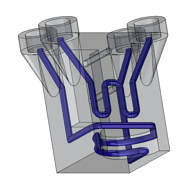
The below above displays the robotic gripper designed, and the internal fluid flow channels are seen in blue color. There are two sets of channels with.
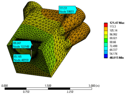
Furthermore, a converged cooling model is seen below. The gripping surface had to be kept below a temperature of 600 degrees Fahrenheit to avoid annealing temperatures for the untreated parts that were to be picked up. Notably, the cooling design also ensured that the overall part temperature was kept cool enough to avoid the hose barb attachments (not seen in image) would also not approach their temperature limit of 350F. The maximum gripping surface temperature after thermal cycling was measured at 93.185F.
A plastic prototype was printed.

